Technical details
Control electronics / software overview:
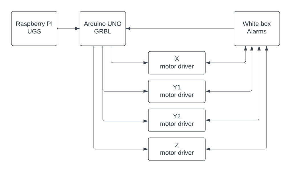
- The user operates the machine using Universal Gcode Sender (UGS) which runs on a Raspberry Pi
- An Arduino running GRBL firmware controls the machine based on the GCODE it receives from UGS
- The 4 stepper motor drivers run the stepper motors based on the STEP/DIRECTION pulses they receive from GRBL
- “White box” is a custom PCB to integrate GRBL with the alarm functionality of the motor drivers.
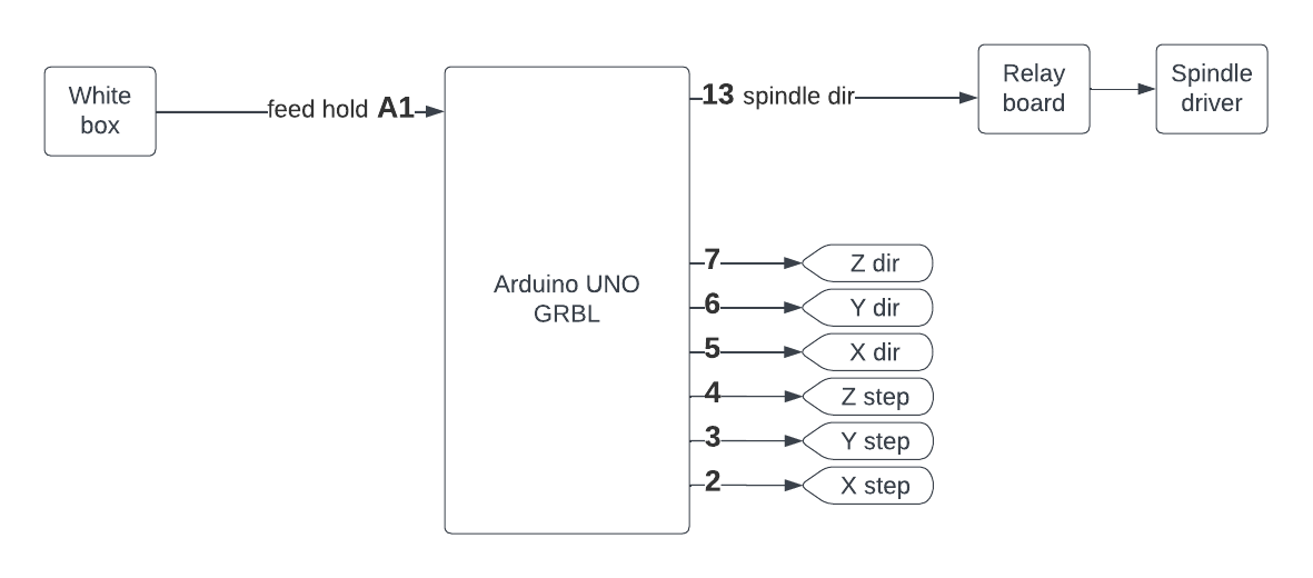
Arduino/GRBL wiring
Alarms and homing
Wiring: 
The “white box” is a custom PCB was developed by Dave Gönner.
He provided me the Schematic and the following description:
The four orientalmotor motor drivers each have the ability to go into an error state when they detect something is wrong. For example when a motor encounters to much friction, or overheats. When an error condition occurs, the driver sets an output signal (the ALARM output) and lights the error LED on the driver.
The other motor drivers need to be notified when an error occurs and they need to stop. It would be very dangerous if for example one of the Y-axis motors stops due to an error, but the other one keeps on going.
The circuit takes the error output signals from all four motor drivers and combines them, and then feeds them back to each driver’s STOP input pin.
So when one of the drivers goes into error, the other three are stopped. The error condition is also forwarded to the arduino running GRBL, so that it can stop processing the file. In theory you can clear the error and continue where you left off, but this depends on the kind of error that happened.
The circuit has a button with an LED in it. It turns on when one of the drivers is in error. By pushing the button, the error condition is cleared and the four drivers are ready to continue.
Spindle
Manual of spindle driver: HY01D523B Variable Frequency Drive
VFD parameters suggestion from humphrey makers:
pD000 = 0 # Parameter Lock - 0:Invalid 1:Valid
pD001 = 1 # Source of Run Commands - 0:Operator 1:External terminal 2:Communication port
pD002 = 1 # Source of Operating Frequency - 0:Operator 1:External 2:Communication port
PD005 = 400 # Max Operating Frequency - 0 to 400 Hz; 400 Hz = 24000 RPM
pD007 = clear # Min Frequency
PD011 = 165 # Frequency lower limit; 165 Hz = 10000 RPM; don't go lower as spindle is air cooled
pD014 = 2
pD015 = 2
pD070 = 1
jumper leftmost (VI to center)
Frequency to RPM calculation:
(Hz x 60 x 2) / number of poles = no-load RPM
Configuration changes made on 22/12/2020:
- Set source of operating frequency
PD2 = 0(was 1). There is no connection to input the frequency from external terminal - Set main frequency
PD3 = 380(was 400). This results in the display showing ~18000 RPM when spindle is running - Set frequency lower limit
PD11 = 165(was 0) - Set number of motor poles
PD143 = 2(was 4) - Set rated motor revolution
PD144 = 24000(was 14400)
Stepper motors and drivers
Drivers: Orientalmotor AZD-K
Motors: AZM69AK