Fusion 360 CAM
This page shows the basics of creating 2D pocket and contour toolpaths.
Setup
In the setup we define the stock (raw material) dimensions and where the origin is
Setup > New
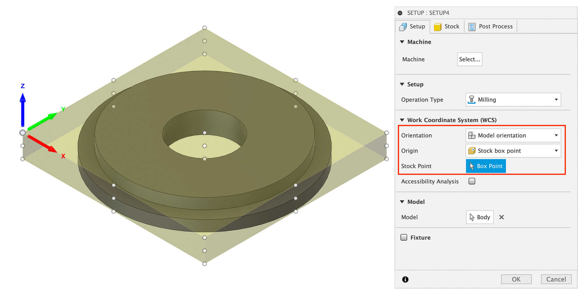 We want the origin to be in the bottom left corner. X,Y and Z should point in the directions as shown in the picture
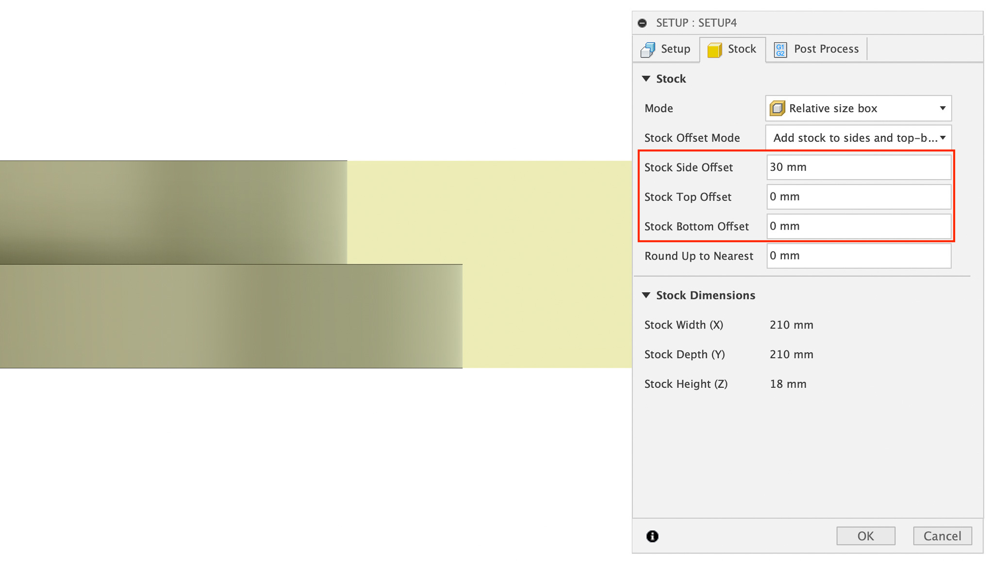 In general we don’t want any stock material above and below our model (
Stock Top Offset = 0 and Stock Bottom Offset = 0)
I use Stock Side Offset = 30 to have space around the model to screw the stock to the sacrificial layer
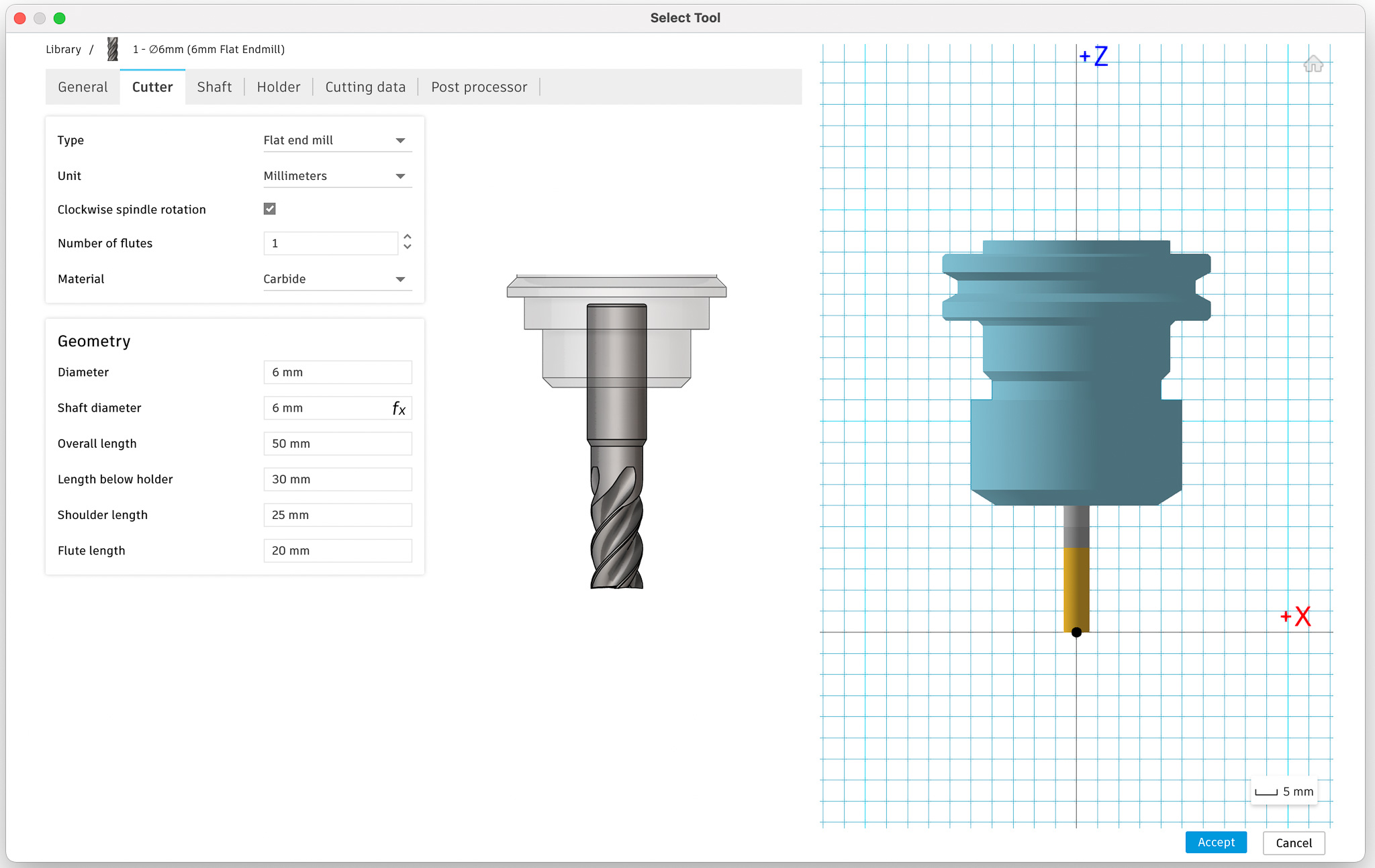
Create tool
Next we’re going to create the tool that is going to be used to mill our model
Manage > Tool Library
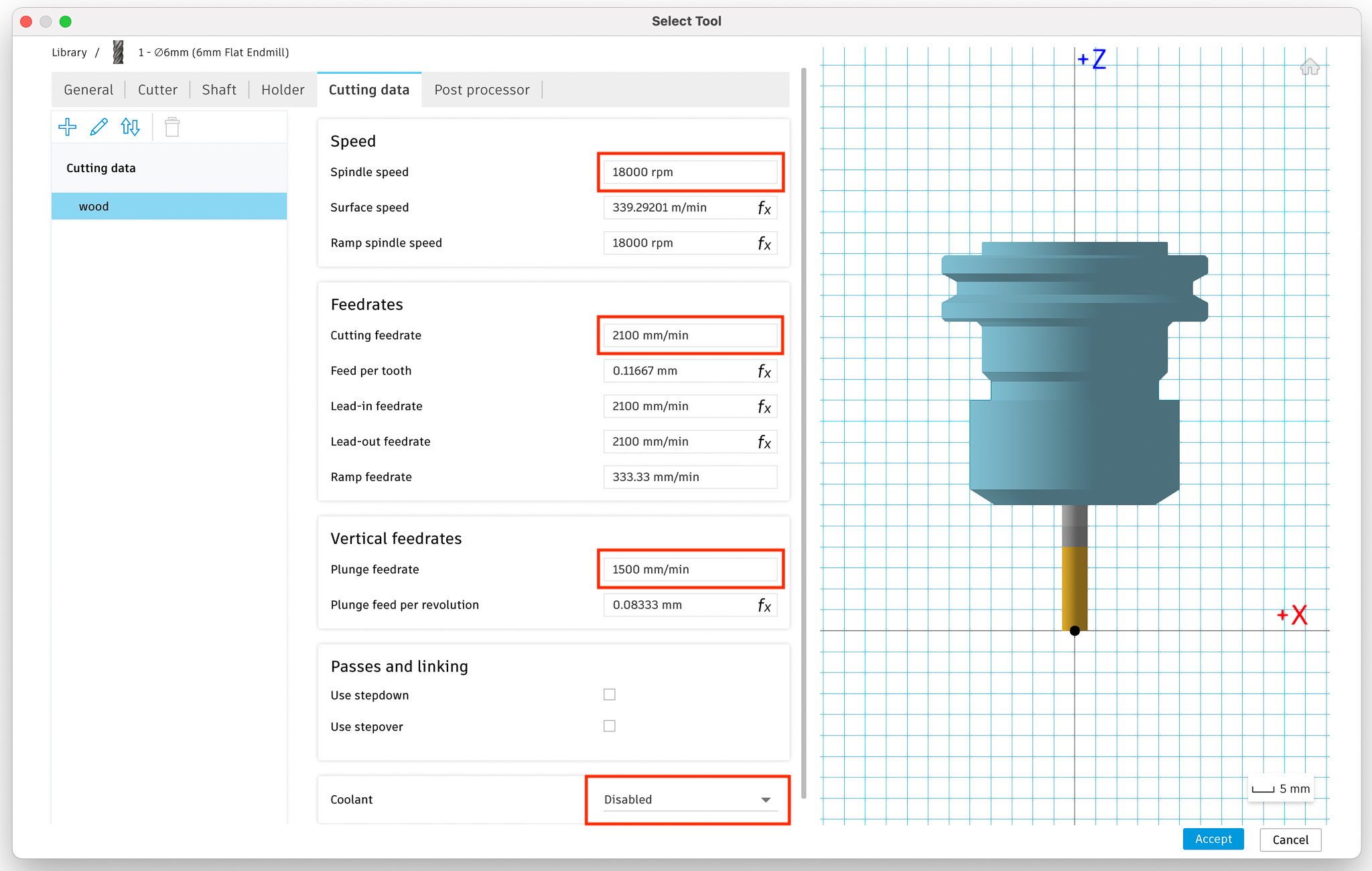
The Cutting feedrate and Plunge feedrate shown here match the one used by Grasshopper when selecting hard wood
2D Pocket toolpath
I use this toolpath to cut a pocket
2D > 2D pocket
Tab: Tool
Select the tool that we created earlier. All the values will be filled in based on the tool settings
Tab: Geometry
Select the part of your model where the pockets should be cut
Tab: Heights
No change needed
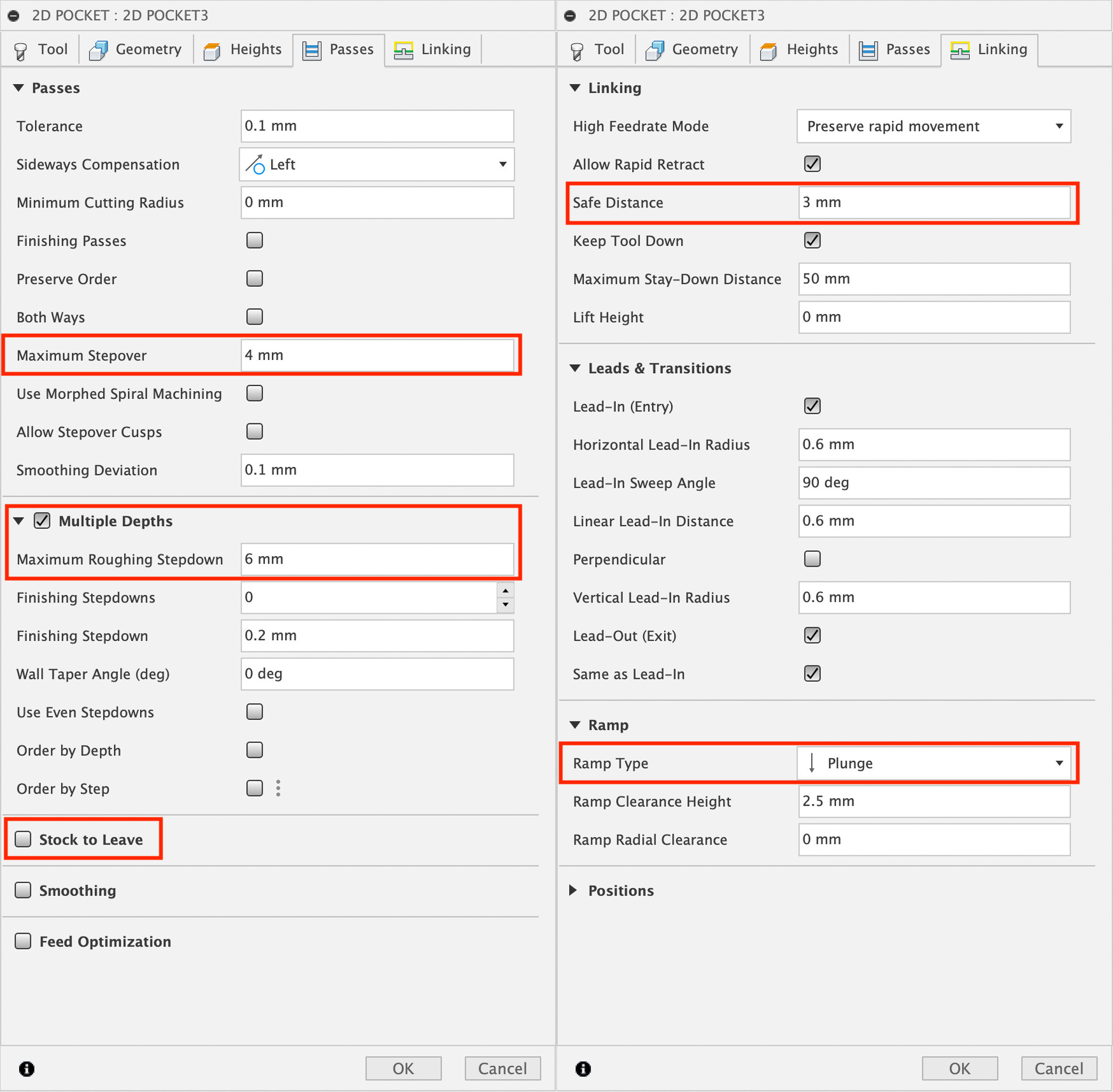
Tab: Passes
Set the Maximum stepover: 75% of the tool diameter is a good starting point. This defines the horizontal distance between passes.
Use Multiple Depths to go to the final pocket depth in multiple steps: 6 mm stepdown is a good starting point
Uncheck Stock to Leave
Tab: Linking
Set Safe Distance = 3 mm
When machining wood, Ramp Type = Plunge can used to speed up things
2D Contour toolpath
I use this toolpath to cut the contour of my model
2D > 2D contour
Tab: Tool
Select the tool that we created earlier. All the values will be filled in based on the tool settings
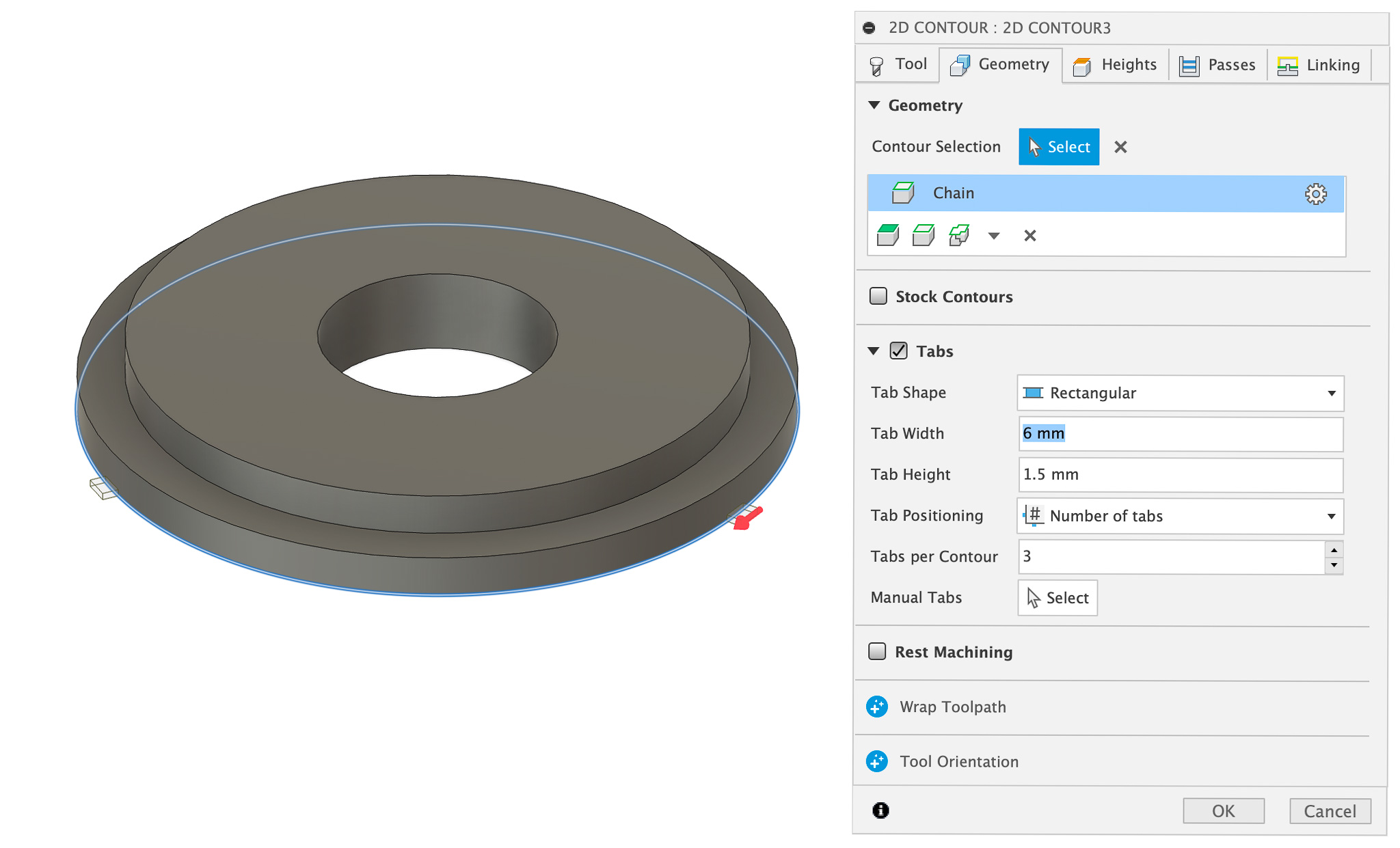
Tab: Geometry
Select the contour that should be cut out Configure Tabs if needed
Tab: Heights
No change needed
Tab: Passes
Use Multiple Depths to go to the final cut depth in multiple steps: 6 mm stepdown is a good starting point
Tab: Linking
Set Safe Distance = 3 mm
Simulate
Once the toolpaths are complete it’s a good idea to simulate them to check that everything looks good.
Actions > Simulate
NC program
Post processor
Download GRBL post processor
Manage > Post Library
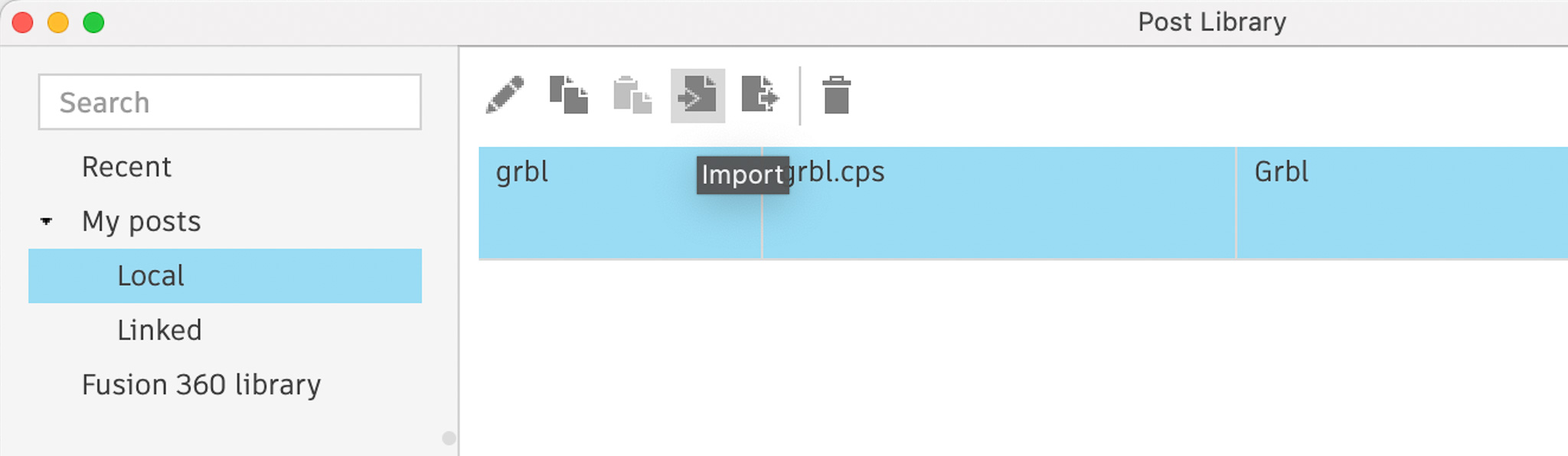
Select Local, click import icon and then select the downloaded file
Create NC program
Right click on Setup > Create NC program
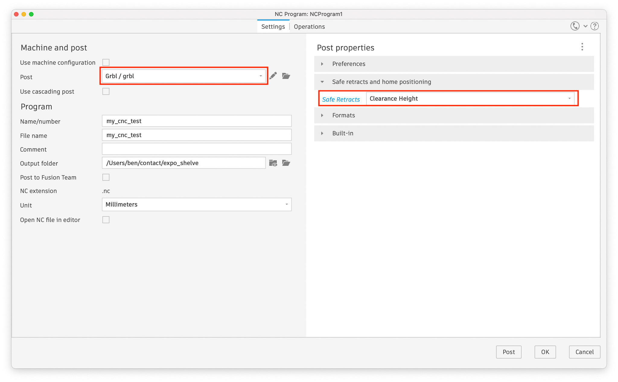
Select the GRBL post processor downloaded earlier and adjust the Safe retracts setting
If Safe retracts setting is not adjusted to Clearance Height the program will make fast moves with the tool in the material. This will ruin the piece, break the tool and potentially damage the machine
The created .NC file can be copied to the machine and executed
Resources
This video is a good introduction to designing and machining simple furniture with fusion 360
The Trace and Engrave toolpaths are suitable for engraving. This video explains the differences between the two.